The 3D Utilities are a java library and set of tools for the loading, viewing, manipulating, and comparison of 3D content from among the many 3D formats that exist today. Though a variety of data structures exists to represent 3D data we build everything on a single simple polygonal mesh data structure allowing most users to deal with the loaded 3D data fairly easily from within their custom applications. In addition, being a fairly low level representation of a 3D surface most other 3D representations can be converted to this representation while the inverse can often be non-trivial.
By fixing our 3D data representation we provide a uniform means of constructing a library of file loaders, model viewers, manipulation methods, and comparison measures. Of particular importance is the effort to construct a large open library of 3D file loaders. To our knowledge there does not exist an active open source library for loading 3D data. Java 3D attempted to provide such a functionality some time ago by providing a ōLoaderö interface by which developers could construct new file loaders. Over the years however very few loaders have been made and distributed. It is possible that the complexity of the very flexible scene graphs used by Java 3D made it a hindrance for all but the more advanced programmers to attempt constructing file loaders. Coupled with the effort required to construct loaders for the many file formats available, many of which being propriety with closed specifications, likely did not help the situation.
It is this projects hope that by ōkeeping things simpleö and imposing this simple mesh data structure we can succeed where others have failed. We hope to encourage programmers at large, both advanced and novice, to contribute file loaders. At the same time we hope to provide a free means of loading a large numbers of 3D formats to developers (in particular new programmers, students, who often re-implement a simple loader to incorporate models in their projects). By developing the library in Java we hope to provide this functionality across platforms and over the web.
In this document we describe the 3D Utilities API including the ōMeshö data structure, the various ōModelViewerö classes implemented to display the loaded models, the ōMeshLoaderö class to load 3D files into meshes, and the ōMeshSignatureö used to compare two meshes. We also describe various included tools such as the ōModelBrowserö used to view an manipulate 3D files in the local file system.
# Library
For the full details of what is available in the 3D Utilities library one should refer to the java documentation. In this document we will give a brief overview of the library and how to use it. Note, all classes described below exist within the package ōedu.ncsa.modelö.
## The Mesh Class
At its heart the ōMeshö class is nothing more than a set of points on the surface of a 3D object and a set of polygonal faces connecting groups of these points together. The points, represented by the ōPointö helper class in ōedu.ncsa.model.MeshAuxiliaryö can be allocated as follows:
```java
Point point = new Point(0.0, 0.0, 0.0);
```
and can be accessed as follows:
```java
System.out.println(point.x + ō, ō + point.y + ō, ō + point.z);
```
Faces, represented by the ōFaceö helper class in ōedu.ncsa.model.MeshAuxiliaryö can be allocated for triangles as follows:
```java
Face face = new Face(0, 1, 2);
```
where the arguments are the indices of vertices in a list of points (with indices starting at 0). The point indices used in the face can then be accessed as follows:
```java
for(int i=0; i<face.v.length; i++){
System.out.println(face.v[i]);
}
```
A mesh is made up of a vector of points and a vector of faces and thus can be allocated as follows:
```java
Vector<Point> vertices = new Vector<Point>();
Vector<Face> faces = new Vector<Face>();
/**
Code to fill in vertices and faces vectors.
**/
Mesh mesh = new Mesh();
Mesh.setVertices(vertices);
Mesh.setFaces(faces);
```
The vertices and faces of a mesh can be later accessed with the ōgetVerticesö and ōgetFacesö method as follows:
```java
for(int i=0; i<mesh.getVertices().size(); i++){
Point point = mesh.getVertices().get(i);
System.out.println(point.x + ō, ō + point.y + ō, ō + point.z);
}
for(int i=0; i<mesh.getFaces.size(); i++){
Face face = mesh.getFaces().get(i);
for(int j=0; j<face.v.length; j++){
System.out.println(face.v[j]);
}
}
```
The Mesh class supports quite a few additional attributes in order to support surface normals, texture, and material properties of the object. However the points and faces encompass the minimum information required to build and view a 3D object within the ōMeshö and ōModelViewerö classes respectivley.
## Mesh Loaders
Though a mesh can be created as described in the examples of the previous section the intended means of loading a mesh is from a file via a class that extends the ōMeshLoaderö abstract class. The ōMeshLoaderö class requires that three methods be implemented:
```java
public String type() {ģ}
public Mesh load(String filename) {ģ}
public boolean save(String filename, Mesh mesh) {ģ}
```
When creating a mesh loader class we suggest naming it as ōMeshLoader_XYZö where XYZ is the extension of the file format that this loader will load (in all caps). Details on what should be implemented for each of the required methods is given below:
* **String type()**
* Return the extension of the format that this loader supports. The returned extension will be used to search through a set of mesh loaders to identify which can open a given file.
* **Mesh load(String filename)**
* Load a mesh from the given file name. This method will open the file, parse it, instantiate a ōMeshö, and at a minimum set its vertices and faces. Note, it is possible to have loaders for formats that do not contain 3D objects represented as vertices and faces. In such cases this method will also have to convert data representations. Once the data is loaded into a mesh, that mesh should be returned.
* **boolean save(String filename, Mesh mesh)**
* Save the mesh passed in as the second argument to the file name specified in the first argument. This method must create an output file of the correct format containing the 3D object stored within the given mesh. Note, the output file format does not have to support 3D objects represented as vertices and faces. In such cases this method will also have to convert data representations. A value of true should be returned if the file was saved successfully.
The loader library currently contains loaders for the following format extensions: *.3ds, *.ac, *.byu, *.cob, *.dae, *.dxf, *.facet, *.geo, *.gts, *.iob, *.jvx, *.kmz, *.lws, *.ms3d, *.nff, *.obj, *.off, *.phd, *.plg, *.ply, *.poly, *.q3o, *.raw, *.sdml, *.stl, *.stp, *.tet, *.tm, *.tri, *.vtk, *.wrl, *.x, and *.x3d. Most of these loaders have been created by the project initiators and involvement in the Google Summer of Code progam. Some additional loaders where included as wrapped Java3D loaders, specifically from the Xj3D project and from NCSA Portfolio (a past NCSA project to provide file loader support in Java 3D).
## Model Viewers
The ōModelViewerö class extends the JPanel class to provide a convenient means of adding 3D viewing and manipulation to a Swing based Java program. The ōModelViewerö class is the only class who has any knowledge of rendering (i.e. how to draw the mesh and the graphics package to render it with). Depending on the particular implementation, the model viewer also provides users with certain functionality to manipulate the mesh. These can be as simple as rotating, zooming, and translating the model or more advanced abilities such as non-photo realistic rendering, meshing, decimation, and warping. The provided model viewers exist within the package ōedu.ncsa.model.graphics.xyzö, where ōxyzö is the name of a particular rendering library. The current distribution contains the following model viewers:
* edu.ncsa.model.graphics.j3d.ModelViewer
* edu.ncsa.model.graphics.jogl.basic.ModelViewer
* edu.ncsa.model.graphics.jogl.ModelViewer
* edu.ncsa.model.graphics.lwjgl.basic.ModelViewer
* edu.ncsa.model.graphics.lwjgl.ModelViewer
* edu.ncsa.model.graphics.jogl2.ModelViewer
It is up to the programmer to decide which they wish to use as each library is different and they may be more comfortable with one over another. Note the model viewers within sub-packages named ōbasicö have only the simplest functionality, specifically flat shaded rendering and manipulation in terms of rotating, scaling, and translating. Those not in a ōbasicö package tend to have much more features in terms of viewing and manipulation.
Below we show a simple example of using a model viewer to display a loaded model using the JOGL library. Note the only thing making this use the JOGL library is the import on the second line. To use a different model viewer and library we would simply change this line.
```java
import edu.ncsa.model.*;
import edu.ncsa.model.graphics.jogl.*;
...
public static void main(String args[])
{
JFrame frame = new JFrame("Model Viewer");
ModelViewer viewer = new ModelViewer();
frame.add(viewer);
frame.setSize(600, 600);
frame.setVisible(true);
Mesh mesh = new MeshLoader_OBJ().load(ōcrank.objö);
viewer.setMesh(mesh);
}
```
An example of the resulting window is shown below. The user can click and drag to rotate the object and right click to reveal additional options within a popup menu.

## Model Signatures
Mesh signatures can be thought of as a sort of hash function. Each takes a 3D model represented as a mesh and turns it into one or more vectors of numbers that are used to represent the given mesh. How this is done varies from simple statistics to more complex features. The purpose of these signatures is to provide a means of comparing two mesh models and determining how similar they are.
In order to create a new mesh signature you should extend the ōMeshSignatureö abstract class. The ōMeshSignatureö class stores the signature as a vector of double arrays named ōsignatureö and requires that three methods be implemented:
```java
public String type() {ģ}
public MeshSignature clone() {ģ}
public void setSignature(Mesh mesh) {ģ}
```
When creating a mesh signature class we suggest naming it as ōMeshSignature_Xyzö where ōXyzö is a name describing this particular implementation. Details on what should be implemented for each of the required methods is given below:
* **String type()**
* Return a string identifying this signature.
* **MeshSignature clone()**
* Create a duplicate of this signature and all its data members.
* **void setSignature(Mesh mesh)**
* Set the signature. This method should accept a mesh as input, perform whatever processing is required on it, and produce the mesh signature.
Several useful methods are inherited from the ōMeshLoaderö class as well. All except ōgetSignatureö assume that the default signature representation of a vector of double arrays is used. If this is not used by your mesh signature then you must overwrite these methods.
* **Object getSignature()**
* Return the constructed signature.
* **double compareTo(MeshSignature s)**
* Compare this mesh signature to another. The two mesh signatures should be of the same type and their signature should use the default ōsignatureö variable represented as a vector of double arrays. If only one double array is used this returns the Euclidean distance between the two signatures. If multiple double arrays are present then it will return the sum of Euclidean distances between each pair of arrays (or vectors).
* **double magnitude()**
* Return the magnitude of the signature (treating it like a vector). Again this assumes that the signature uses default ōsignatureö variable represented as a vector of double arrays. If only one double array is used this returns magnitude of that one array. If multiple double arrays are present then it will return the sum of the magnitudes of the arrays (or vectors).
* **save(String filename)**
* Save the signature to a text file of the given name.
* **load(String filename**
* Load a signature from a text file of the given name.
The provided mesh signatures exist within the package ōedu.ncsa.model.signatureö. The current distribution contains the following mesh signatures:
* **MeshSignature_Statistics**
* Based on vertex statistics such as the mean and standard deviation of their positions. Very fast to compute. Sensitive to size and orientation of the model.
* **MeshSignature_SurfaceArea**
* The sum of the area of all faces. Fairly fast to compute. Sensitive to size, somewhat sensitive to shape.
* **MeshSignature_LightField**
* Based on the work of [Chen, 2003], the light fields method compares silhouettes from various viewing angles around the model. Fairly fast to compute. Sensitive to the shape of convex hull, ignores rigid transformations.
* **MeshSignature_SpinImage**
* Based on the work of [Johnson, 1999], spin images are constructed as 2D histograms of the angles and distances of vertices neighboring a given vertex. In this implementation a spin image is created for every vertex and averaged to create a spin image for the entire model. Computationally expensive to compute. Sensitive to relative vertex positions. Ignores surface and is invariant to rotations and translations. Not invariant to scale however. Tends to capture a somewhat high level notion of two things being similar.
* **MeshSignature_SpinImages**
* Based on the work of [Johnson, 1999], spin images are constructed as 2D histograms of the angles and distances of vertices neighboring a given vertex. In this implementation a spin image is created for every vertex and stored separately. Computationally expensive to compute. Sensitive to relative vertex positions. Ignores surface and is invariant to rotations and translations. Not invariant to scale however. Tends to capture a somewhat high level notion of two things being similar. This version compares vertices independently and as such is designed to find one model within another model (i.e. a sub-part).
Below we show a simple example of using a mesh signature to compare two models:
```java
import edu.ncsa.model.*;
import edu.ncsa.model.signature.*;
...
public static void main(String args[])
{
Mesh mesh1 = new MeshLoader_OBJ().load(ōbunny.objö);
Mesh mesh2 = new MeshLoader_DAE().load(ōhorse.daeö);
MeshSignature_LightField signature1 = new MeshSignature_LightField();
MeshSignature_LightField signature2 = new MeshSignature_LightField();
signature1.setSignature(mesh1);
signature2.setSignature(mesh2);
System.out.println(ōSimilarity = ō + signature1.compareTo(signature2);
}
```
# Tools
The 3D Utilities library comes with several executable tools as well. Below we describe each of them.
## Model Convert
Using the included library of file loaders we provide a conversion utility executed in Windows through ōModelConvert.batö and on Mac/Linux through ōModelConvert.shö. This command line utility can be used by typing the following at the command prompt:
```dos
> ModelConvert file.abc file.xyz
```
The above command loads the ōfile.abcö file using the ōMeshLoader_ABCö loader into a ōMeshö object then through the ōMeshLoader_XYZö loader's save method exports the model to ōfile.xyzö. Note, the 3D Utilities folder must be in your path for the ōModelConvertö command to be found. In order for this converter to function there must be corresponding loaders with the required functionality implemented.
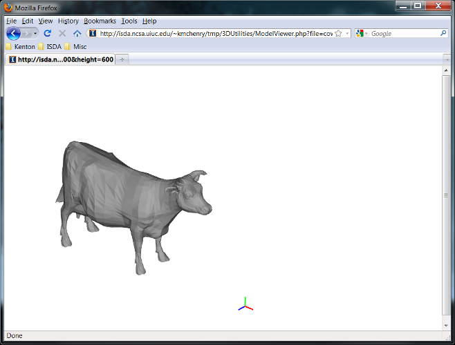
## Model Viewer Applet
To display 3D content on web pages we have created the ōModelViewerAppletö class which wraps the JOGL ōModelViewerö class as an applet. Using this and the very basics for loading, displaying, and manipulating wavefront *.obj files we provide a java archive ōModelViewerLite.jarö that is created from the projects build file. We recommend using this jar as opposed to the full ō3DUtilities.jarö which contains everything, as this will need to be downloaded in the background as users view web pages which utilize its functionality and thus it is desirable to make the file as small in size as possible.
An example of how to call and use the applet can be found in the ModelViewer.php file. The output of this is shown in the figure below. You can call this PHP script directly from a web browser by installing a web server on your machine, copying ModelViewerLite.jar and ModelViewer.php to the public directory and from your browser going to:
```
http://localhost/ModelViewer.php?file=file.obj&width=600&height=600
```
to load the file ōfile.objö. Note, this assumes you have a wavefront file, "file.obj", is in that same public directory.
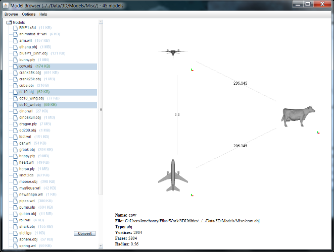
## Model Browser
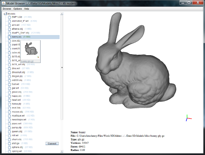
The ōModelBrowserö utility allows a user to see all 3D models found by searching recursively beneath a selected folder (shown in the figure above). The found 3D models, displayed in the left panel, can be selected and viewed/manipulated in the right area through an embedded ōModelViewerö panel. Additional features include: the ability to create image thumbnail images of all found 3D models, the ability to filter out specific file types, and the ability to select multiple 3D files simultaneously and compare them both visually and quantitatively via a selected ōMeshSignatureö (shown in the figure below).
You can run the tool on Windows with the ōModelBrowser.batö file and on Mac/Linux with the ōModelBrowser.shö file. Before running the tool you should configure it by editing the files ōModelViewer.iniö and ōModelBrowser.iniö. The parameters in ōModelViewer.iniö are as follows:
* **LoadPath**
* The default path to use when loading new models from the right mouse button popup menu.
* **ExportPath**
* The path to export files to when ōExportö is selected from the right mouse button popup menu.
* **MetaDataPath**
* The path to store metadata in such as signatures and thumbnails.
* **Signature**
* The signature to use. Should be set to the fully qualified name of the class including the package (e.g. ōedu.ncsa.model.signatures.MeshSignature_lightFieldö)
* **RebuildSignatures**
* True if signatures should be rebuilt each time the model is loaded. If false the signature will be constructed only the first time the model is loaded.
* **DefaultModel**
* The default model to load. This model will be shown when the model viewer first starts.
* **Adjust**
* True if the loaded model should be scaled and centered to fit in the window. If false the model will be loaded as is in the file.
The parameters in ōModelBrowser.iniö are as follows:
* **LoadPath**
* The default path to use when loading new models from the right mouse button popup menu.
* **MetaDataPath**
* The path to store metadata in such as signatures and thumbnails.
* **Polyglot**
* The URL to a Poyglot web server. The Polyglot server will be used to convert files that have no supporting loaders into a format that is supported.
* **ConvertableList**
* A file containing a line separated list of file extensions that can be converted to a loadable format using the above set Polyglot service.
* **TransparentPanels**
* True if split pane panels should be transparent. If set to transparent then viewed models in the model viewer pane when translated or zoomed sufficiently will be visible behind the left file pane and behind the bottom file data pane.
* **WiiMote**
* True if Wii-mote support should be enabled. A connected Wii-mote can be used to rotate, translate, and zoom into the model within the model viewer.
* **RebuildThumbs**
* True if thumbnails should be rebuilt. If false the thumbnails will only be built if they donÆt exist already, otherwise, the previously built thumbnails will be used.